House Framing Diagrams From Foundation to Roof
A house framing diagram is not just a page of labels.
Stud. Joist. Header. Rafter. Plate. Those names matter, but the real job of the drawing is to show how the house stands up, how loads move, where openings interrupt that path, and which parts have to keep working together from foundation to roof.
That is the part worth learning first. Once you stop reading these diagrams like a lumber glossary and start reading them like structure, they get much easier to follow.
Start with the main views that do the real work: the whole-house frame, floor framing, wall framing, openings, roof framing, bracing, connectors, and load path.
What House Framing Diagrams Are Really Showing
A house framing diagram usually does one of four jobs.
- It shows the whole structure. Floor, walls, roof, and openings tied together.
- It isolates one assembly. Floor framing, wall framing, roof framing, or a detail by itself.
- It explains a connection. A corner, an opening, a roof-to-wall condition, a floor edge, a brace, a hold-down.
- It shows load path. Not just what the parts are called, but where the forces are going.
The mistake is expecting every drawing to do all four at once. The cleaner the diagram, the more likely it is focused on one job.
Start with the Whole-House View
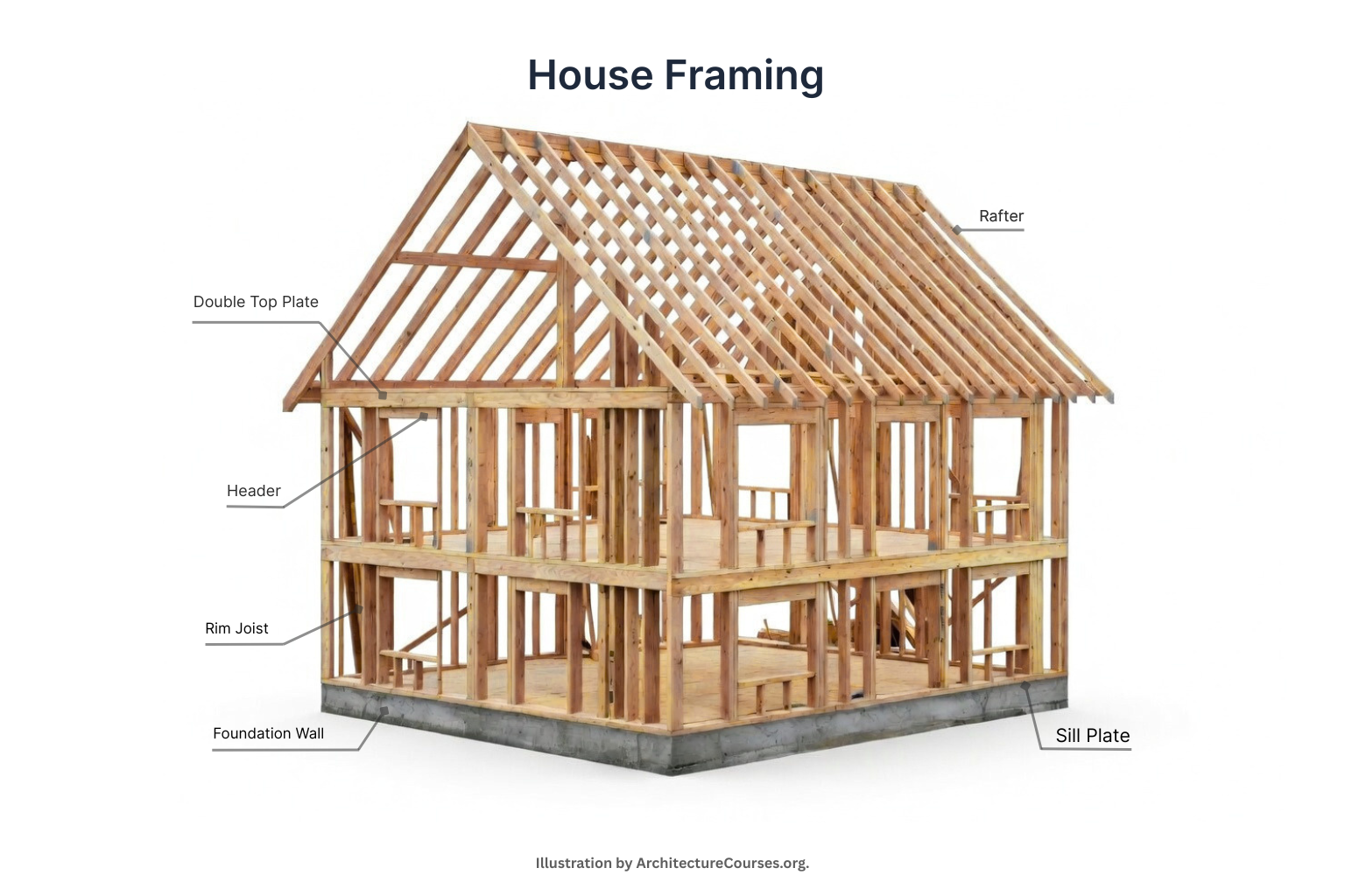
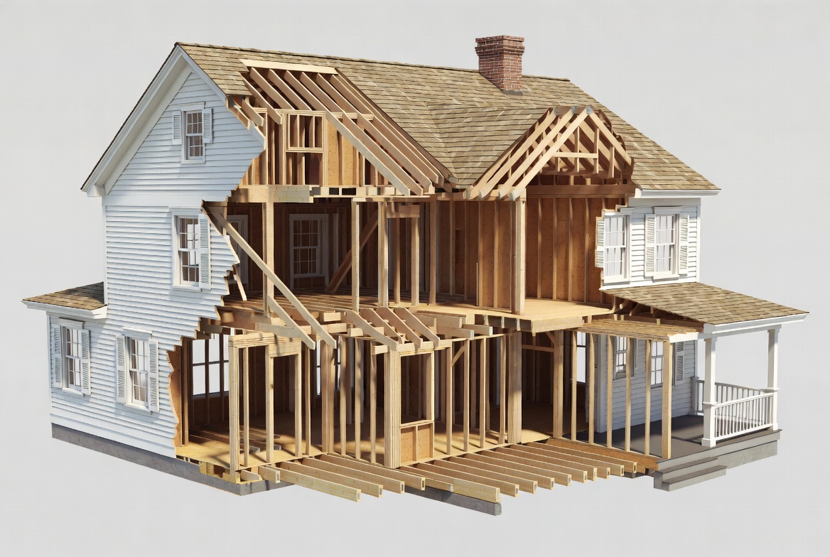
Illustration by ArchitectureCourses.org. Whole-house framing overview showing how the foundation, floor, walls, openings, and roof work together as one structural system.
The broad house framing diagram is the one most readers picture first. It usually shows the house from foundation up to roof in one simplified view.
This is the drawing that helps you understand sequence. The foundation carries the floor. The floor becomes the platform for the walls. The walls carry the roof. Openings interrupt wall framing, so the framing has to route loads around them instead of pretending they are not there.
Before you get too far into studs and rafters, remember that the structure still starts lower than the diagram often wants to admit. For the support below the frame, see house foundations before construction.
| Part of the House | Main Members | What the Diagram Is Usually Trying to Show |
|---|---|---|
| Foundation | Footing, foundation wall, anchor bolts, sill plate | Where the frame begins and how loads reach the ground |
| Floor | Sill, joists, rim, beam, subfloor | How the platform is built and where spans and bearing begin |
| Walls | Bottom plate, studs, top plates, sheathing | How vertical framing repeats and where loads move downward |
| Openings | Headers, king studs, jack studs, rough sill | How loads move around doors and windows |
| Roof | Rafters or trusses, ridge, ties, bracing, sheathing | How the top of the house is supported and tied back into the walls |
Floor Framing: Read Direction First
Floor framing diagrams are where the structure starts feeling less decorative and more honest.
A basic floor framing drawing will usually show the sill line, joist direction, rim condition, subfloor above, and sometimes a beam or bearing point below.
The first thing to read is direction. Which way are the joists spanning? Where are they landing? What is carrying them?
A lot of beginners look at the subfloor and assume that is the main floor structure. It is not. The joists and their support lines are doing the heavy work. The subfloor ties the surface together and helps the floor act more like one platform, but it is not the same thing as the framing system below it.
Floor diagrams also tell you what the rest of the house is allowed to do. Room layout, stair openings, plumbing runs, stiffness, bounce, and some wall locations all start getting shaped here.
Wall Framing: The Pattern and the Interruptions
Wall framing diagrams are the first ones many readers feel comfortable with because the repetition is obvious.
Bottom plate. Studs. Double top plate. Sometimes blocking. Sometimes sheathing.
But the drawing matters most where the repetition stops.
Regular stud spacing is easy. Openings, corners, intersections, fire blocking, and top conditions are where the diagram starts earning its keep. That is why a wall framing diagram should not just be read as a pattern. It should be read as a system that has to carry load, support sheathing, hold finishes, and stay straight enough that the later work still fits.
For a closer look at ordinary wall layout, read how to frame a wall and wall framing basics. Once the discussion shifts from bare studs to rigidity and enclosure, exterior wall sheathing is the better next step.
Openings: Where the Load Path Changes
Openings are where framing drawings stop being comfortable.
A wall with no openings is repetitive. A wall with openings has to reroute load. That is what the opening diagram is really about.
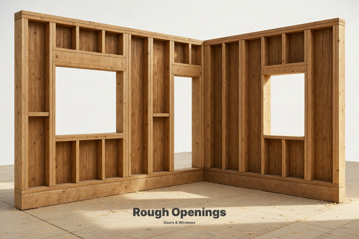
Window Framing Diagrams
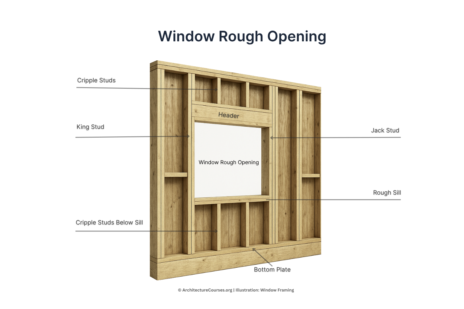
Illustration by ArchitectureCourses.org. Window rough opening framing diagram showing the main structural parts around a standard window opening.
A basic window framing diagram usually shows a header, king studs, jack studs, a rough sill, and cripple studs above or below depending on the condition being shown.
The important thing is not memorizing the names first. It is seeing the logic. The opening removes studs from a wall line, so the framing has to bridge over the opening and carry the load around it.
Door Framing Diagrams
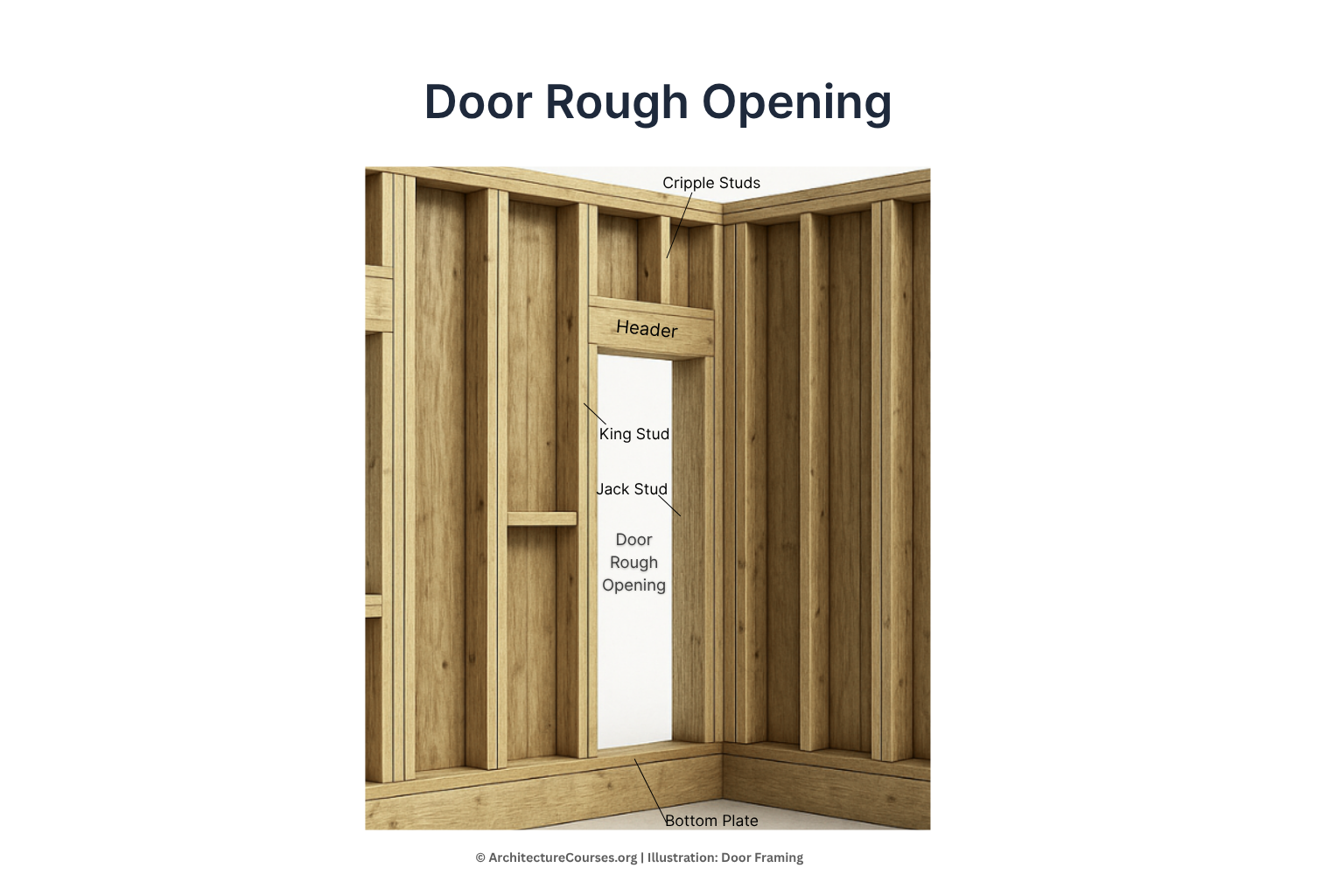
Door framing is similar, but simpler in one obvious way: the opening runs to the floor. You still need the load transferred above the opening, which is why the header and side support matter.
These diagrams are where weak framing becomes visible fast. Sticking doors, cracked trim, sloppy rough openings, and bad load transfer usually start here.
For deeper opening details, see window rough openings, window header framing, jack stud framing, and king and jack stud framing.
Roof Framing: Shape Is Not the Same as Structure
Roof framing diagrams confuse people because they are trying to show geometry and structure at the same time.
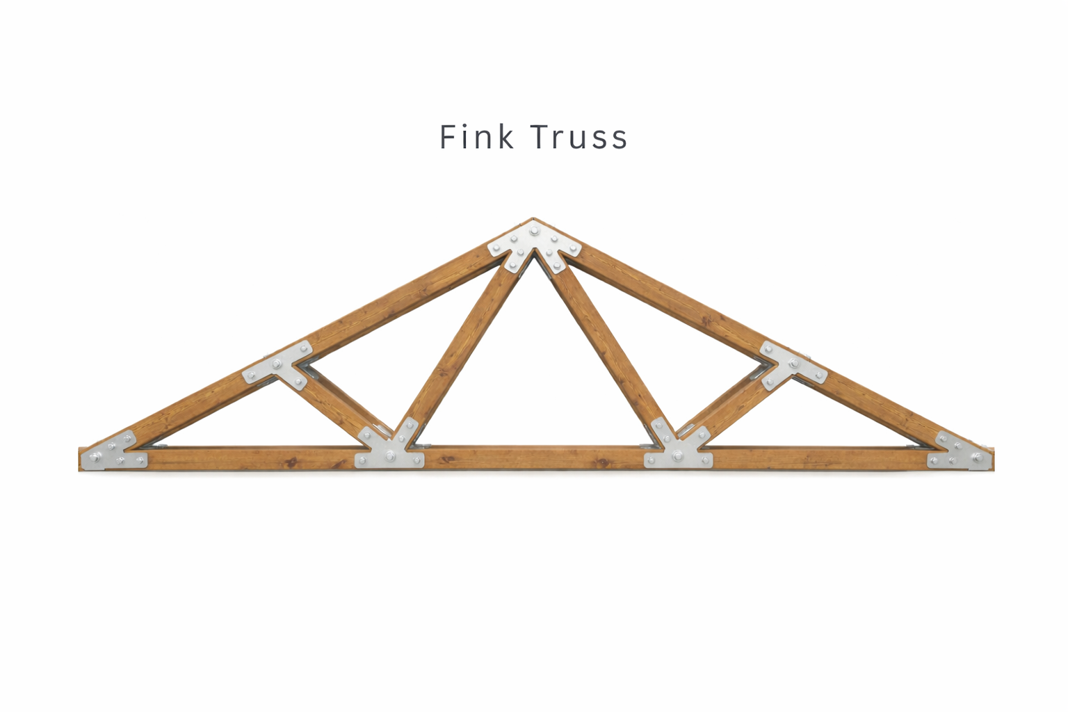
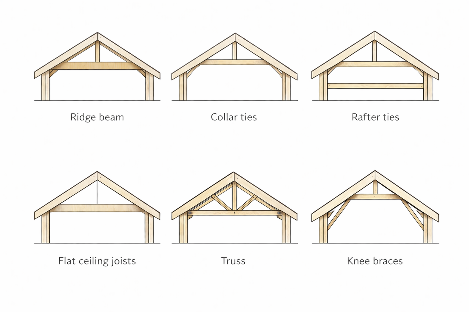
A simple roof framing diagram usually shows rafters or trusses, ridge condition, ceiling joists or ties where relevant, and the roof plane above. That sounds manageable until the roof shape gets more complicated.
Gable roofs are the cleanest starting point because the pattern is easier to read. Hip roofs, intersecting roofs, dormers, and more broken-up forms make the drawing harder because the framing directions, support logic, and bracing needs stop repeating so neatly.
Roof drawings also get misread when people confuse a ridge board with a ridge beam. A ridge board mainly aligns rafters. A ridge beam is structural and carries load. That difference matters a lot more than it sounds.
If you want more on roof structure and support, see introduction to roof structures. For bracing and roof stability, types of roof bracing and gable braces are the useful follow-ups.
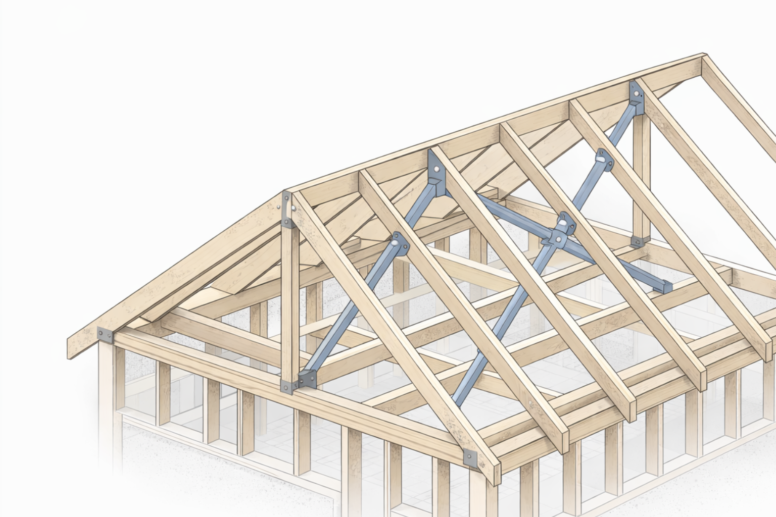
Bracing and Connectors: The Small Parts That Keep the House Acting Like One Structure
A lot of framing diagrams get taught as if the big members do everything and the smaller parts are just hardware.
That is not how the house behaves.
Joist hangers, anchor bolts, hold-downs, metal ties, straps, and roof-to-wall connectors are what keep the load path continuous when gravity, wind, and uplift start asking harder questions. These pieces do not always dominate the drawing, but they often decide whether the structure behaves like one system or like a stack of separate guesses.
On floor diagrams, a joist hanger is telling you where a member is being supported instead of just resting on top of something. On wall diagrams, a hold-down or tension device is telling you that lateral force matters there, not just vertical weight. On roof diagrams, hurricane ties and similar connectors tell you the roof is not only sitting on the wall. It is tied to it.
For more on that roof-to-wall connection logic, see roof-to-wall connections and truss bracing and roof support systems.
Vertical Bracing Path and Lateral Load Path Are Not the Same Diagram
This is one of the cleaner upgrades you can make in the way you read framing drawings.
| Type of Load Path | What It Is Following | What You Look For in the Diagram |
|---|---|---|
| Vertical load path | Gravity loads moving downward | Roof to wall, wall to floor, floor to foundation, foundation to soil |
| Lateral load path | Wind or seismic force moving sideways | Sheathing, braced wall lines, shear walls, hold-downs, anchors, roof and floor diaphragms |
Vertical load path is the easier one to see first. Roof loads move into walls. Walls move loads to floors and foundations. Openings interrupt that path, so headers and side support reroute the force.
Lateral load path is the part many beginners miss. Wind does not care that the studs are labeled nicely. The house still needs sheathing, bracing, anchors, and connectors to keep the frame from racking out of shape.
Once you separate those two ideas, a lot of confusing diagrams stop feeling random.
Basic Framing Terms That Matter in Diagrams
You do not need one hundred parts memorized to read a framing diagram well. You do need the terms that keep showing up in the important places.
| Term | What It Does | Why It Matters in a Diagram |
|---|---|---|
| Sill plate | The first wood member anchored to the foundation | It marks where the frame begins above concrete |
| Rim joist | The perimeter board closing off the joist ends | It helps define the edge of the floor platform |
| Header | The member spanning over an opening | It shows where the wall is rerouting load |
| King stud | Full-height stud beside an opening | It keeps the wall pattern legible at windows and doors |
| Jack stud | Shorter stud carrying the header | It helps transfer opening loads downward |
| Ridge board | Non-structural board aligning rafters | It is easy to confuse with a structural ridge beam |
| Ridge beam | Structural beam supporting rafter tops | It changes the support logic of the whole roof |
| Wall sheathing | Panel layer that helps stiffen the wall | It starts the lateral-force conversation, not just enclosure |
| Shear wall | Wall section resisting lateral load | It tells you the drawing is showing more than gravity framing |
| Hold-down | Connector resisting uplift and tension at wall ends | It marks critical points in the lateral load path |
Platform Framing vs. Balloon Framing
This comparison matters because it changes the way the whole-house diagram reads.
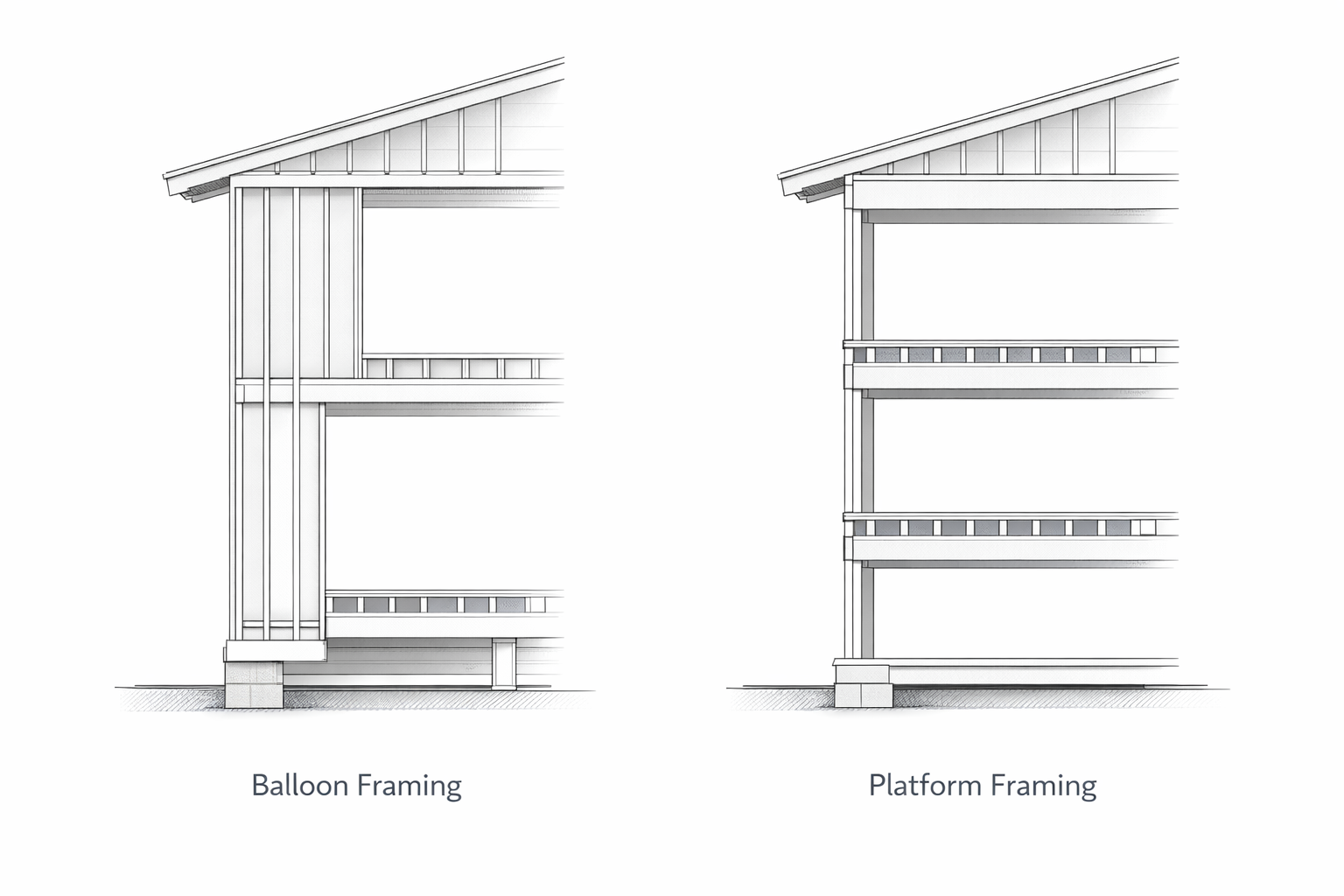
In platform framing, one floor is built first, then the walls for that level stand on that platform, then the next floor platform starts above. In balloon framing, wall studs run past the floor line for a longer continuous height.
Most modern houses are platform framed because the sequence is simpler, safer, and easier to control on site. Balloon framing still matters because older houses may be built that way, and the diagram reads differently once you know what you are looking at.
| System | What the Diagram Tends to Show | Why It Matters |
|---|---|---|
| Platform framing | Each floor built as its own platform with walls stacked level by level | Cleaner sequencing and easier load reading in most modern house diagrams |
| Balloon framing | Longer continuous wall studs running past floor lines | Important in older houses because fire blocking, repairs, and wall reading change |
Two-Story House Framing Diagrams Are Where Alignment Starts Mattering More

A two-story house framing diagram is not just a taller version of the one-story drawing.
The first-floor walls, the second-floor platform, the upper walls, and the roof all start stacking in a way that makes bad alignment easier to spot. Bearing lines matter more. Floor framing has more authority over wall location. Load path mistakes become less forgiving because the house has more chances to drift out of agreement with itself.
That is why two-story diagrams are useful for learning. They make it easier to see which members line up cleanly and which conditions need extra framing decisions to keep the structure honest.
Read It Like This, Not Like This
| Read It Like This | Not Like This | Why It Works Better |
|---|---|---|
| Start with support and load path | Start with whatever label is easiest to recognize | The structure makes more sense once you know what is carrying what |
| Check which members repeat and which interrupt the pattern | Treat every piece as equally important | Interruptions usually reveal the real structural decisions |
| Read openings as rerouted load zones | Read them as empty spaces with trim around them | Doors and windows are where the wall logic changes |
| Look for span direction and bearing points | Look only at the finished room shape | Framing cares about support first and room shape second |
| Separate structure from enclosure | Assume sheathing, finishes, and framing all do the same job | The wall gets easier to understand once the jobs are separated |
What People Usually Misread in House Framing Diagrams
- They think every wall is doing the same kind of work. Some walls are carrying more than others. Some are mainly partition logic. The drawing usually gives that away if you slow down.
- They ignore direction. Joists, rafters, and spans all care about direction. The plan stops making sense if you skip that.
- They treat openings like decoration problems. Openings are structural interruptions first.
- They confuse enclosure with structure. Sheathing matters, but it is not the same thing as the core frame.
- They read roof shape without reading support logic. Roof forms are easy to admire from outside and easy to misunderstand in a framing drawing.
- They miss the small connectors. A strap, hanger, anchor, or hold-down may look minor on paper and still decide the whole load path.
- They forget the foundation is still part of the story. The frame is only as legible as the support below it.
Why Real Framing Never Looks Like the Clean Diagram
This helps people more than another label list usually does.
Real framing on site is messier. Lumber crowns. Plates need shimming. The foundation is rarely as perfect as the diagram suggests. Openings need adjustment. A beam lands close to where the plan wanted it, not exactly where the teaching diagram pretended it would.
Good diagrams strip that noise out so you can see the rule. That is useful. Just do not confuse diagram clarity with jobsite neatness.
The cleaner the drawing, the more it is helping you understand the structure. The rougher the site, the more the crew has to keep that structure working under less-than-clean conditions.
How These Diagrams Happen on Site
One reason framing diagrams make more sense on site than on paper is that the build sequence helps explain them.
- foundation and sill line
- floor framing
- wall framing
- openings and bracing logic
- upper floor framing if the house has another level
- roof framing
- sheathing and enclosure work
That order is not just scheduling. It is structural logic. The next layer needs the one below it to be true enough first.
For the sequence side of the job, see construction planning and scheduling.
Sheathing Diagrams Matter More Than They Get Credit For
A lot of people think the “real” framing stops once the studs, joists, and rafters are drawn. That is too narrow.
Sheathing is where a lot of structural behavior starts getting tied together. It helps floors act more like platforms, walls act more like diaphragms, and roofs act more like unified surfaces instead of loose member collections.
For more on that layer, read House Sheathing 101. If the question is more roof-specific, exterior roof sheathing and replacing roof sheathing pick up that part of the story.
FAQ
What is a house framing diagram?
It is a drawing that shows how the structural members of a house are arranged and how they work together. Some diagrams show the whole house. Others isolate floors, walls, openings, roofs, connectors, or specific details.
What should I learn first in a framing diagram?
Learn load path first. Once you understand where the loads are moving, the member names start making more sense.
What is the difference between a framing plan and a framing diagram?
A framing plan is usually more layout-based and plan-oriented. A framing diagram is often simplified to explain one structural idea clearly.
Why are window and door framing diagrams so important?
Because openings interrupt the wall framing pattern and force the structure to reroute load. They are where the drawing stops being repetitive and starts showing real structural decisions.
Why do roof framing diagrams confuse people so much?
Because they are trying to explain geometry, direction, support, and connection at the same time. The shapes are familiar from outside, but the framing logic underneath is less obvious.
What is the easiest house framing diagram for a beginner?
Usually a simple whole-house framing overview or a basic wall framing diagram. Those show the repeating structure before the harder conditions start stacking up.
What is the difference between vertical load path and lateral load path?
Vertical load path follows gravity loads downward through the house. Lateral load path follows wind or seismic force through sheathing, bracing, anchors, and connectors.
Are sheathing diagrams part of framing, or are they a separate topic?
They are part of the larger framing story because they help tie the structural members together, even if they are often taught after the basic skeleton.