Architectural drawings are not one thing.
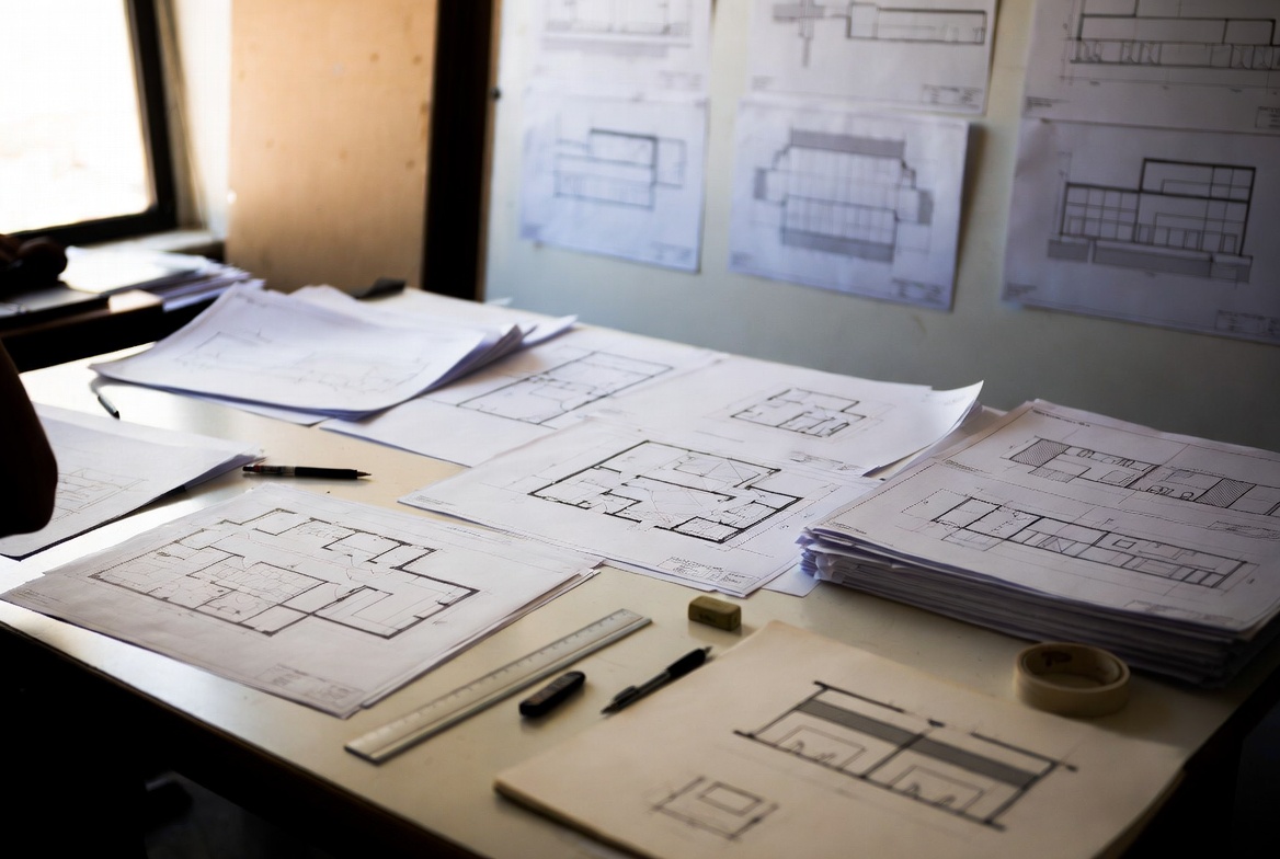
A small house renovation may need a few plans, elevations, sections, and schedules. A hospital, airport, school, or high-rise can need hundreds of sheets once consultants, code reviews, shop drawings, and record drawings enter the job.
The point of a drawing list is control. It tells the team what has to be shown, where to find it, and which sheet answers which question.

| Reader | Drawings to Know First | Why They Matter |
|---|---|---|
| Architecture student | Site plan, floor plan, elevations, sections, RCP, basic details. | These are the backbone of studio drawings and exam work. |
| Homeowner or beginner | Floor plans, elevations, sections, site plan, door and window schedules. | These explain layout, exterior appearance, height, setbacks, and openings. |
| Contractor | Plans, sections, schedules, details, demolition plans, coordination sheets. | These prevent guessing on site. |
| Practicing architect | The full drawing set, consultant sheets, shop drawings, record drawings, and closeout documents. | The architect has to coordinate the package, even when other people produce many of the sheets. |
Do You Have to Know All 67 Drawings?

No.
Different roles need different levels of knowledge. A student does not need to understand curtain wall shop drawings in depth. A homeowner does not need to read a full MEP coordination set. A licensed architect coordinating consultants does.
Practicing architects
Architects working on full permit and construction sets need to understand the whole package. Even when engineers produce the structural, mechanical, electrical, plumbing, and fire-protection sheets, the architectural set still has to coordinate with them.
The main risk is not that one drawing looks bad. The risk is that two drawings disagree.
- Floor plan shows one wall type.
- Wall section shows another.
- Door schedule calls for a fire rating the plan does not show.
- Reflected ceiling plan places a fixture where a duct has to run.
That is where real jobs get expensive.
Architecture students
Students should focus on the backbone first: title sheet, site plan, floor plans, elevations, sections, reflected ceiling plan, door and window schedules, and a few basic details.

If you can explain those clearly, you are in good shape. The rest comes later.
Home contractors and renovation builders
Small contractors do not need every drawing in a large commercial set. They do need the drawings that control permits, layout, demolition, structure, stairs, openings, and finishes.
- Site plan for zoning and permit review.
- Floor plans for layout and wall locations.
- Elevations for exterior work.
- Sections for stairs, roofs, basements, and floor heights.
- Schedules for doors, windows, and finishes.
- Demolition plan for renovation work.
For the broader foundation, start with Architectural Drawing Basics.
67 Types of Architectural Drawings
Core architectural drawings

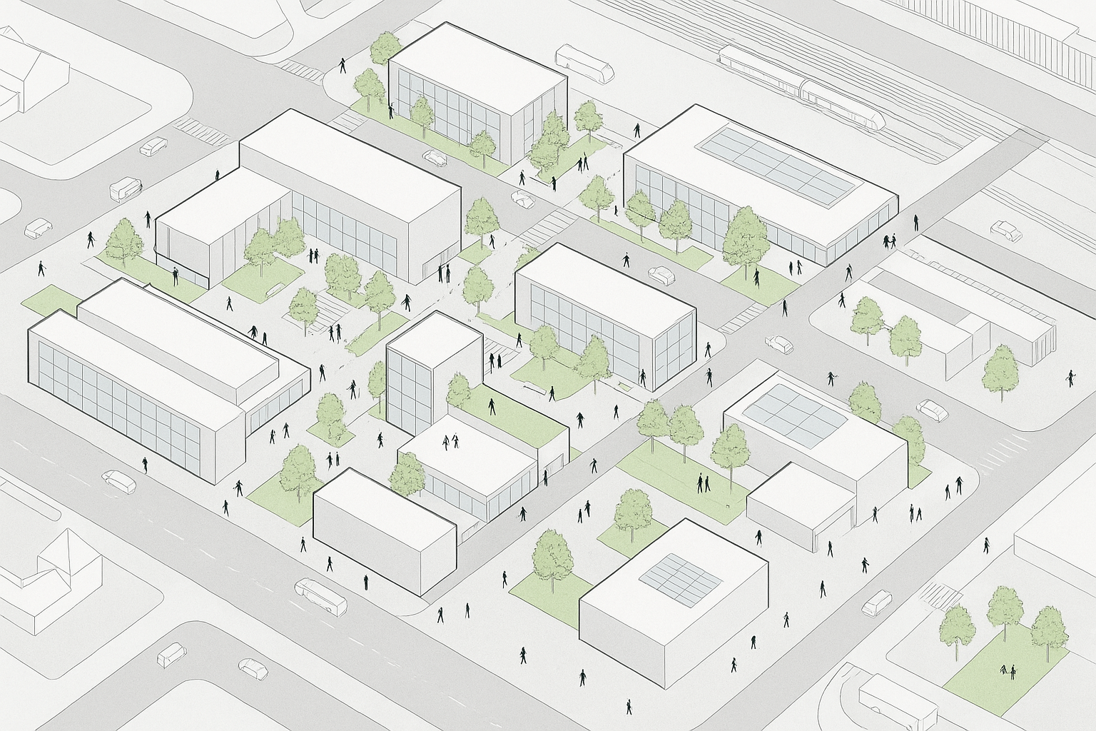
Image by ArchitectureCourses.org. Stacked drawing sheets show how architectural information builds into a coordinated set, not one single drawing.
1. Title Sheet
The title sheet frames the whole set. It usually includes the project name, address, sheet index, project team, code summary, drawing issue date, and revision history.
2. General Notes
General notes cover rules that apply across the project. They may include code notes, material standards, dimension rules, accessibility references, and construction assumptions.
3. Key Plan
A key plan shows where the current drawing sits inside a larger building or site. It matters most on schools, hospitals, campuses, towers, and phased projects.
4. Abbreviation and Symbol Legends
These explain shorthand, symbols, tags, and graphic conventions. Without a legend, “SD” might mean smoke detector, sliding door, or something else depending on the drawing discipline.
5. Site Plan
The site plan shows the building on the land. It usually includes property lines, setbacks, streets, walks, driveways, utilities, grading, and major site features.
6. Landscape Plan
A landscape plan shows planting, paving, grading, site furniture, drainage zones, and outdoor areas. On some projects, this drawing is as important as the building plan because water and access problems start outside.
7. Floor Plans
Floor plans are the backbone of most architectural sets. They show walls, rooms, doors, windows, stairs, fixtures, dimensions, and circulation.

8. Roof Plan
A roof plan shows ridges, slopes, drains, scuppers, parapets, roof equipment, access hatches, and sometimes fall-protection points.
9. Roof Drainage Layout
This drawing focuses on how water leaves the roof. It may show roof drains, crickets, scuppers, gutters, downspouts, overflow drains, and slope direction.
10. Reflected Ceiling Plan
A reflected ceiling plan, or RCP, shows what happens overhead: light fixtures, ceiling grids, soffits, diffusers, sprinkler heads, access panels, and ceiling heights.
For basic plan-reading, see How to Draw Your Own House Blueprints.
11. Enlarged Plans
Enlarged plans zoom into areas where the main floor plan cannot show enough detail. Bathrooms, kitchens, stairs, labs, lobbies, and reception desks often need them.
12. Demolition Plans
Demolition plans show what stays, what goes, and what needs protection. In renovation work, this sheet can prevent crews from removing the wrong wall, fixture, pipe, or finish.
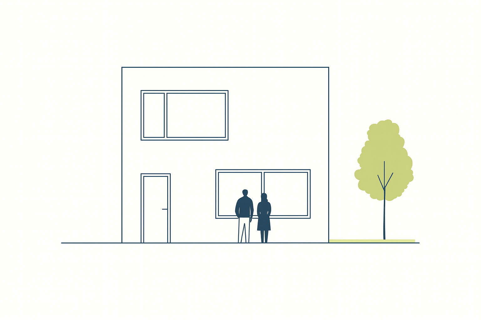
13. Elevations
Elevations are flat views of the building faces. They show exterior materials, openings, heights, rooflines, trim, grade changes, and façade rhythm.
14. Building Sections
A building section cuts through the project to show height, floor levels, roof shape, wall assemblies, structure, stairs, ceiling zones, and vertical relationships.

Construction and Working Drawings
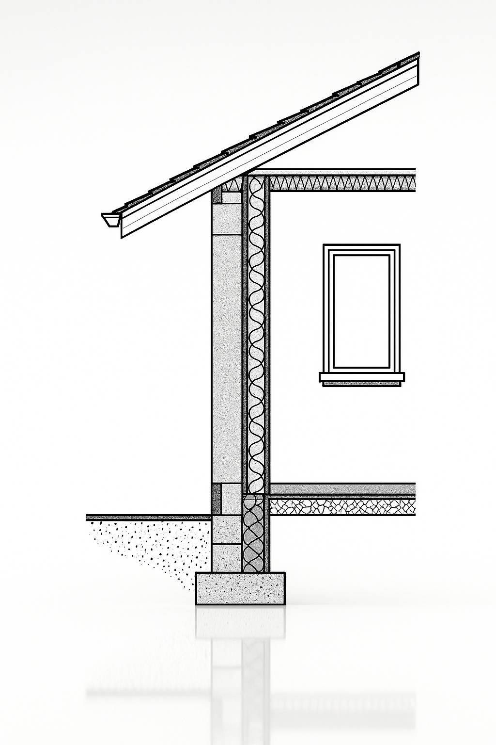
15. Wall Sections
Wall sections show how a wall is built from foundation to roof. They may include structure, insulation, air barriers, vapor control, cladding, flashing, finishes, and fire-stopping.
16. Foundation Plans
Foundation plans show footings, slabs, piers, piles, grade beams, foundation walls, anchor bolts, and bearing points.
17. Structural Framing Plans
These show beams, joists, trusses, columns, bearing walls, bracing, and structural layout. They must align with the architectural plans.
18. Slab and Reinforcement Drawings
These drawings show slab thickness, control joints, reinforcement, rebar spacing, thickened edges, and special slab conditions.
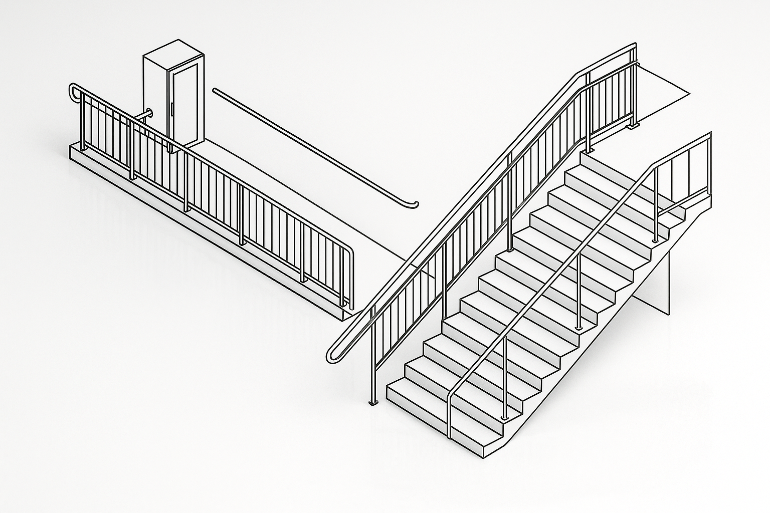
19. Stairs and Ramp Details
Stairs and ramps need more than a line on a plan. The drawings must show rise, run, landings, slope, headroom, handrails, guards, nosings, and clearances.

20. Door Schedules
A door schedule lists every door, size, material, rating, frame type, hardware group, swing, and remarks.
21. Window Schedules
Window schedules track window type, size, operation, glazing, frame material, energy performance, and location.
22. Finish Schedule
A finish schedule tells the team what goes on floors, walls, ceilings, bases, trims, and special surfaces in each room.
23. Floor Finish Plans
These plans show floor material layout, transitions, patterns, thresholds, control lines, and finish changes.
24. Partition Types and Interior Wall Types
Partition type drawings define wall assemblies. They may show fire ratings, acoustic ratings, stud size, layers of gypsum board, insulation, and wall thickness.
25. Ceiling Details
Ceiling details explain soffits, bulkheads, slopes, coves, ceiling transitions, access panels, and difficult overhead junctions.
Code and Compliance Sheets
26. Code Compliance Sheets
These sheets show how the project meets code. They may include occupancy, construction type, allowable area, fire ratings, egress, accessibility, energy compliance, and special local requirements.
27. Fire and Life Safety Plans
Fire and life safety plans show exits, travel distances, rated walls, fire doors, exit signs, sprinklers, alarms, extinguishers, and areas of refuge.
28. Accessibility Drawings
Accessibility drawings show clearances, turning spaces, ramp slopes, bathroom layouts, reach ranges, door maneuvering space, and accessible routes.
29. Phasing and Construction Sequencing Plans
Phasing plans show how a project is built in stages. They matter when a school, hospital, airport, office, or store has to stay partly open during construction.
Interior and Specialized Drawings

30. Interior Elevations
Interior elevations show walls from inside the room. They are used for cabinetry, tile, fixtures, built-ins, equipment, wall finishes, and mounting heights.
31. Casework Details
Casework details explain cabinets, counters, shelves, panels, hardware, reveals, support conditions, and joints.
32. Millwork Shop Drawings
Millwork shop drawings are usually produced by the fabricator. They refine custom woodwork, built-ins, reception desks, wall panels, and specialty interiors before fabrication.
33. Kitchen Layouts
Kitchen layouts show appliances, counters, sinks, clearances, storage, exhaust, plumbing points, power, and work zones.
34. Bathroom Layouts
Bathroom layouts show fixtures, partitions, accessories, clearances, turning space, grab bars, slopes, drains, and wall finishes.
35. Furniture Plans
Furniture plans show desks, beds, seating, tables, workstations, built-ins, and circulation around movable objects.
36. Lighting Plans
Lighting plans show fixture locations, switching, control zones, emergency lighting, dimming, and lighting intent.
37. Power and Data Plans
These show outlets, panels, low-voltage drops, data points, floor boxes, equipment feeds, and coordination with furniture.
38. Acoustical Plans
Acoustical plans identify sound-control treatments, absorptive panels, acoustic ceilings, isolation assemblies, and special rooms that need sound control.
39. Signage and Wayfinding Drawings
These drawings show room signs, directional signs, exit signs, code signage, building identification, and mounting locations.
For a simpler first-house example, see Drawing of a Modern House.
Mechanical, Electrical, and Plumbing Coordination
40. Mechanical Equipment Layouts
Mechanical layouts show HVAC equipment, clearances, access zones, mechanical rooms, rooftop units, boilers, chillers, pumps, and major ducts.
41. Ductwork Routing
Ductwork drawings show duct sizes, paths, diffusers, returns, dampers, fire dampers, and coordination with structure and ceilings.
42. Plumbing Riser Diagrams
Riser diagrams show vertical plumbing runs. They help trace water supply, drainage, venting, stacks, and connections between floors.

43. Fire Protection Layouts
Fire protection drawings show sprinkler heads, standpipes, fire department connections, hose valves, alarms, and protected zones.
44. Electrical Power Plans
Electrical power plans show receptacles, circuits, panels, equipment feeds, conduits, disconnects, and coordination with walls and furniture.
45. Panel Schedules
Panel schedules list circuits, loads, breaker sizes, panel names, and electrical distribution information.
46. Low Voltage and IT Drawings
These drawings cover data, security, Wi-Fi, AV systems, cameras, access control, intercoms, and network rooms.
47. Energy and Sustainability Sheets
These may include energy-code compliance, daylight diagrams, envelope performance, LEED documentation, mechanical performance notes, or sustainability targets.
Shop and Fabrication Drawings
48. Curtain Wall Shop Drawings
Curtain wall shop drawings show mullions, anchors, glazing, gaskets, drainage paths, slab-edge conditions, and panel sizes.
49. Structural Steel Shop Drawings
Steel shop drawings show beams, columns, plates, bolt holes, welds, connections, erection marks, and fabrication instructions.
50. Precast Concrete Shop Drawings
Precast shop drawings show panel sizes, reinforcement, embeds, lifting points, connections, finishes, and installation sequence.
51. HVAC Shop Drawings
HVAC shop drawings refine duct routing, equipment locations, hanger points, access requirements, and mechanical coordination.
52. MEP Coordination Shop Drawings
These overlay mechanical, electrical, plumbing, and fire-protection systems so trades do not fight for the same ceiling space, shaft, or chase.
53. Stone and Masonry Shop Drawings
These show stone panels, masonry units, anchors, joints, coursing, sizes, supports, and installation details.
54. Interior Fit-Out Shop Drawings
Fit-out shop drawings cover custom partitions, ceilings, millwork, fixtures, wall systems, and specialty interior assemblies.
Details That Stop Field Guessing
55. Door and Window Details
These details show heads, jambs, sills, thresholds, sealants, flashing, anchors, and how openings meet the wall.
56. Wall and Slab Junction Details
These show how walls meet floors, slabs, foundations, balconies, terraces, and structural edges.
57. Expansion Joint Details
Expansion joint details show how a building moves without cracking finishes, structure, cladding, or waterproofing.
58. Waterproofing Details
Waterproofing details show membranes, laps, drains, terminations, protection boards, sealants, and vulnerable transitions.
59. Roof Edge and Flashing Details
Roof edge details show parapets, coping, drip edges, flashings, gutters, scuppers, and roof membrane terminations.
60. Stair Details
Stair details show treads, risers, landings, guards, handrails, nosings, stringers, headroom, and code clearances.
61. Elevator Shaft Drawings
These coordinate shaft size, pit depth, overhead clearance, rail supports, doors, machine rooms, controls, and structural openings.
62. Curtain Wall Anchor Details
Anchor details show how façade systems connect back to slabs, beams, embeds, and structural supports.
63. Firestopping Details
Firestopping details show how penetrations through rated walls and floors are sealed around pipes, ducts, conduits, joints, and shafts.
Closeout and Record Drawings
64. As-Built Drawings
As-built drawings show what changed during construction. They are often based on contractor redlines and field records.
65. Record Drawings
Record drawings are cleaned-up final drawings prepared after construction, usually based on as-built information. They become the reference set for future work.
66. Operation and Maintenance Manuals
O&M manuals are not drawings by themselves, but they often link to equipment drawings, maintenance diagrams, schedules, and system information.
67. Maintenance and Access Drawings
These show roof access, ladders, hatches, catwalks, crawlspaces, service corridors, equipment access zones, and safety points for future maintenance crews.
The Scale of a Full Drawing Set
A full drawing set can grow fast.
A small residential project might stay under 30 sheets. A custom house with structural engineering, interior details, millwork, lighting, and landscape work can pass that. A commercial project can move into hundreds of sheets once consultants and shop drawings are included.
That is why drawing order matters. Without a system, nobody knows where to look.
Where Drawing Lists Go Wrong

Drawing lists fail when they are treated like paperwork.
The problem usually shows up as a missing sheet, a vague detail, or two drawings that contradict each other. A stair shown one way in plan and another way in section. A window schedule that does not match the elevation. A wall type that changes from the plan to the detail. A ceiling drawing that ignores the ductwork above it.
One bad drawing can be fixed. A bad set makes everyone guess.
FAQ
Do architects use all 67 drawings on every project?
No. Small projects may use 10 to 30 sheets. Complex commercial projects can use far more.
What is the difference between as-built drawings and record drawings?
As-built drawings show field changes, usually marked by the contractor. Record drawings are the cleaned-up final reference set prepared after construction.
Which drawings should architecture students focus on first?
Site plans, floor plans, elevations, sections, reflected ceiling plans, schedules, and basic details. That is the core set.
Why are door and window schedules separate from floor plans?
Because the plan cannot carry everything. Schedules hold sizes, types, ratings, hardware, glazing, materials, and remarks.
Are shop drawings part of the architect’s drawings?
Not usually. Shop drawings are produced by fabricators, suppliers, or subcontractors. The architect reviews them for general conformance with the design intent.
How many sheets are in a typical residential drawing set?
A simple residential set may have 12 to 30 sheets. Larger custom homes, additions, and renovations can need more, especially when structure, energy, interiors, or site work are involved.
Which drawings do contractors look at most?
Floor plans, elevations, sections, schedules, and details. Those sheets answer most field questions.
Why do inspectors care about accessibility drawings?
Because accessibility is measured. Clearances, slopes, turning spaces, door maneuvering areas, and fixture locations have to work on paper before they work in the field.
Can you build without reflected ceiling plans?
On very small projects, sometimes. On larger or more coordinated work, skipping the RCP creates problems with lights, diffusers, sprinklers, soffits, and ceiling heights.
What is the biggest drawing mistake?
Poor coordination. A drawing can look clean and still be wrong if it disagrees with another sheet.
Who reviews fire and life safety plans?
Fire marshals, building officials, code consultants, and design teams may all review them depending on the project.
Are furniture plans always required?
No. They are often skipped in simple residential work. They matter more in offices, hotels, dorms, classrooms, restaurants, and public buildings where circulation and egress depend on layout.
How detailed should wall sections be?
Detailed enough to show what the builder cannot safely guess: structure, insulation, air and vapor control, waterproofing, fire rating, cladding, and finish layers.
What do phasing plans show?
They show how construction happens in stages. They are especially important when part of the building stays open during work.
Do students need to know shop drawings?
Yes, but not in deep fabrication detail. Students should know who produces them, why architects review them, and how they differ from design drawings.
How are ceiling details different from reflected ceiling plans?
The RCP shows layout. Ceiling details explain the hard parts: soffits, edges, joints, slopes, access panels, and transitions.
What happens if window schedules are wrong?
Wrong sizes, wrong glass, wrong operation, wrong ratings, or failed energy compliance. Window mistakes get expensive fast.
Do renovation projects need demolition plans?
Yes. Demolition plans tell crews what to remove, what to protect, and what must stay.
How do contractors use finish schedules?
They use them to know what material goes in each room. Without the schedule, finishes turn into field questions.
Are acoustical plans necessary?
They are necessary when sound matters: theaters, schools, studios, hospitals, offices, apartments, and performance spaces.
Who produces record drawings?
The architect usually prepares them using contractor-provided as-built information, depending on the contract.
Do landscape plans matter on small jobs?
Yes, especially when grading, drainage, paving, planting, or access affects the building.
Are panel schedules checked by inspectors?
Electrical inspectors often review panel schedules, loads, breakers, and circuits before approval.
What is the minimum drawing set for a kitchen renovation?
Usually a floor plan, demolition plan if needed, interior elevations, appliance layout, finish schedule, lighting plan, and power plan.
Why standardize drawing lists?
So every sheet has a place. A clear drawing order lets architects, engineers, contractors, and reviewers find information without hunting through a messy set.