Architectural Drawing Types and Their Real Uses
Architectural drawings are the backbone of every project. They turn an idea into something that can be priced, permitted, and built. No drawing means no building.
They have evolved over time. What began as hand sketches on parchment became ink on drafting tables, then CAD, and now full 3D BIM models. Each step made drawings sharper, faster, and more reliable, but their purpose has never changed: to show how an idea becomes real.
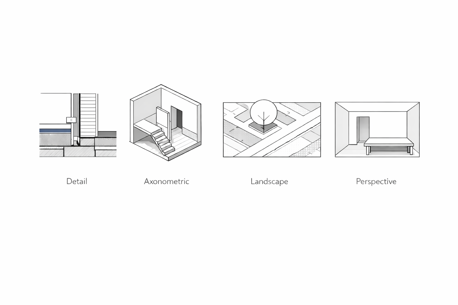
Illustration by ArchitectureCourses.org. Cutaway diagram of a 1910s house basement waterproofing assembly.
Below we break down every major type of architectural drawing. From first sketches to construction sets, you’ll see what each one does, why it matters, and how architects, engineers, and builders actually use them.
Architectural drawing explained in full. See how sketches, site plans, details, and permits connect design to construction.
Architectural drawings are the working language of design. They explain ideas to clients, guide builders, satisfy permits, and record what was built. From rough sketches to full construction sets, every drawing has a clear role.
MUST READ
Blueprint Reading: Construction Drawings for the Building Trade by Sam Kubba
If you struggle with reading drawings, this is the book. Step-by-step, with hundreds of illustrations, it walks you through site work, foundations, structure, interiors, and finishes. It also covers CAD, ANSI/ISO standards, and the symbols every architect and builder actually use.
Are Architectural Drawings, Construction Drawings, Plans, and Blueprints the Same Thing?
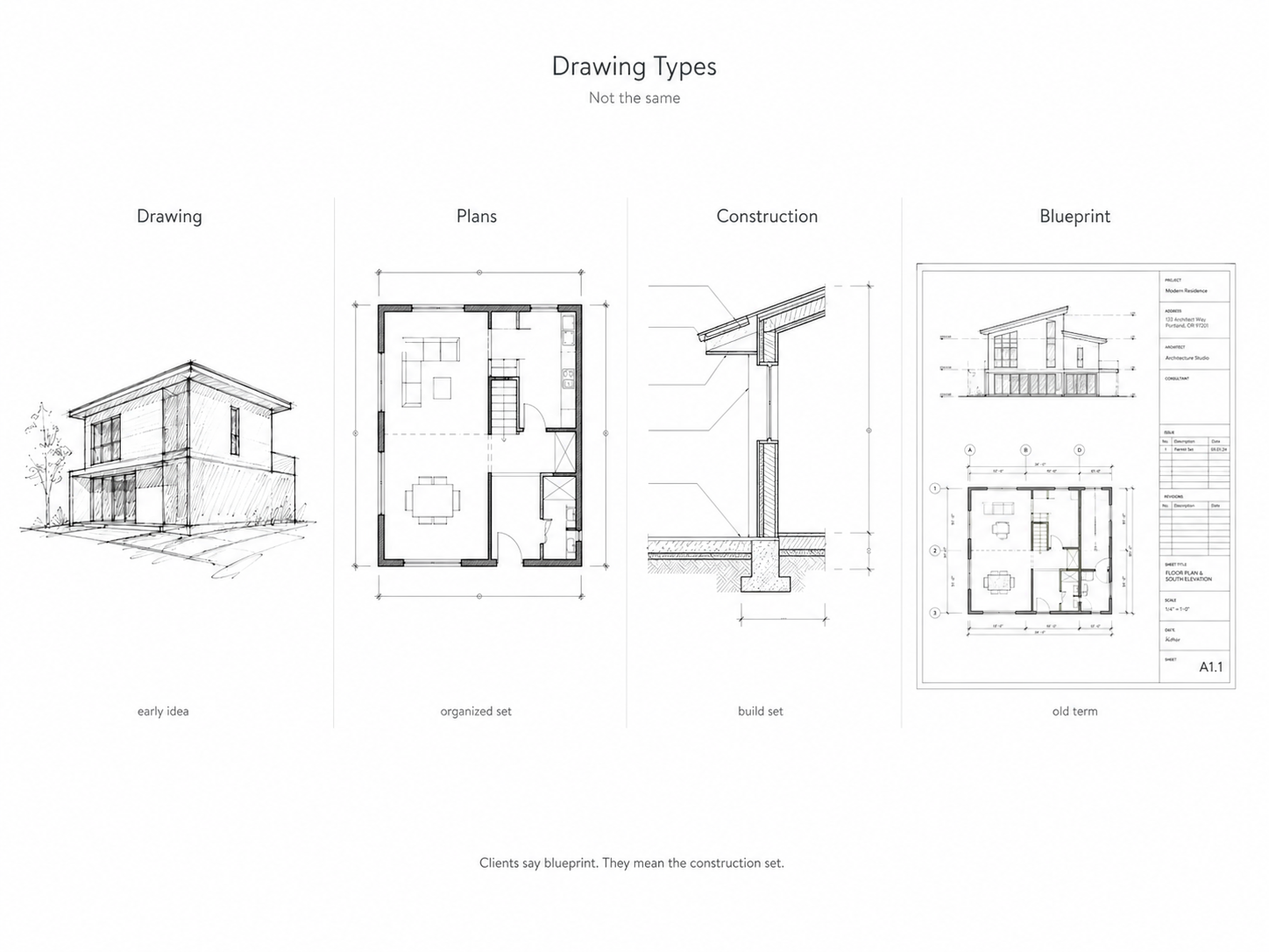
The short answer is no. They overlap, but each has its own role. People often throw these words around like they mean the same thing. They don’t.
What an Architectural Drawing Is
An architectural drawing is any sketch or diagram an architect makes to explain a design. It can be a rough pencil sketch on trace paper or a polished CAD file. The key is that it shows ideas before they’re built.
What Plans Mean
Architectural plans are the organized set of drawings. These include floor layouts, elevations, sections, and details. They show the building as a whole, not just quick ideas.
What Construction Drawings Do
Construction drawings are the technical and legal versions of the plans. They are precise, filled with dimensions, notes, codes, and material specifications. These are what contractors and permit offices rely on.
Why People Still Say Blueprint
Blueprints come from an old reproduction method that left white lines on a blue sheet. The process is outdated, but the word stuck. When someone asks for “the blueprints,” they mean the full construction set.
What This Looks Like in Practice
Picture a modern house project. The architect begins with loose sketches of massing and layout. Those grow into full plans with floor and elevation drawings. Then the construction drawings are prepared for permits and the builder. And when the client asks for the blueprints, what they actually get is the stamped construction set.
See also: How to Read Blueprints: A Complete Guide for Beginners
Why Every Building Starts With a Drawing
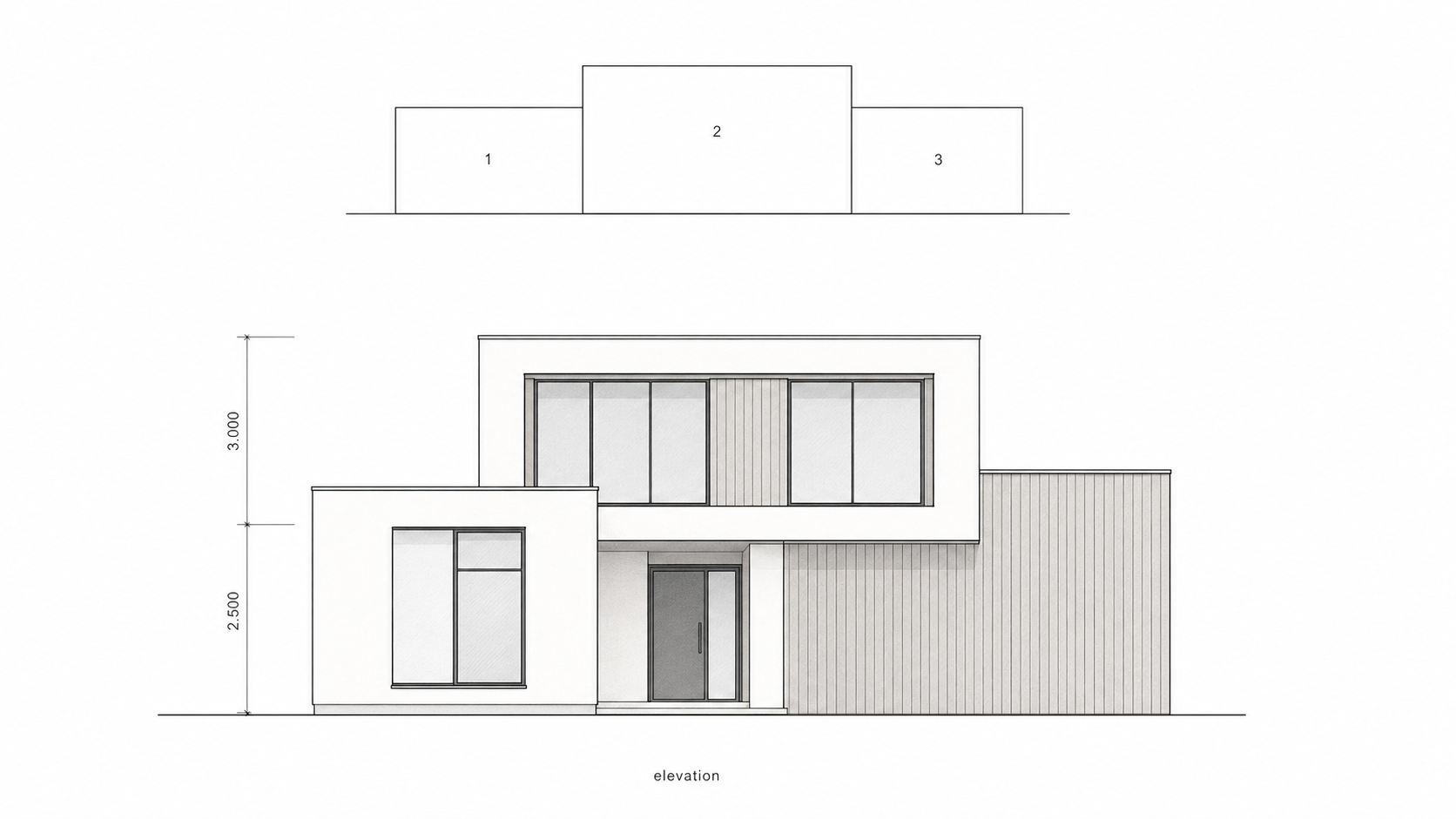
Illustration by ArchitectureCourses.org. A clean front elevation paired with a simple three-part massing diagram to show how the house composition is built from stacked volumes.
The Power of Architectural Drawings
A farmhouse, a stadium, or a skyscraper all began as a drawing. What looks like lines on paper is the first step to anything built.
From Idea to Structure
A drawing turns an idea into measurable space, height, and material. It is the bridge between imagination and construction. Without drawings, bridges would not hold and towers would never rise.
What Drawings Reveal
A floor plan shows how life moves through rooms. A section reveals the hidden bones of walls and floors. An elevation fixes how the outside world will see the building.
More Than Technical Documents
Architectural drawings are proof of thought and records of progress. From stone sketches to digital BIM models, the story of architecture is really the story of drawings.
Without Them, Nothing Gets Built
Drawings do not just describe buildings. They make them possible.
FIELD PICK
Beginner’s Guide to Reading Schematics, 4th Edition by Stan Gibilisco
Clear guide for anyone dealing with wiring or electronic diagrams. Simple explanations, new illustrations, and practical projects. Buy on Amazon
How to Read Architectural Drawings

Illustration by ArchitectureCourses.org. North arrows show drawing orientation on floor plans, site plans, and roof plans, while true north shows the building’s real-world orientation.
Reading drawings is not guesswork. It’s a skill. Builders, students, and clients learn to read lines, symbols, and proportions as a language. The goal is to see not just what’s drawn, but why it’s drawn that way.
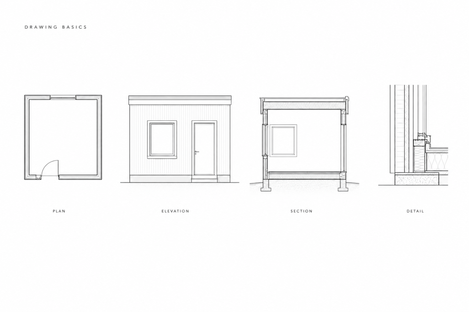
Start with the Basics
Always check the title block first. It tells you scale, date, author, and sheet number. Skip it, and you’ll be lost.
Next comes scale. A 1:100 plan shows massing. A 1:20 detail might show a door hinge. Without scale, every assumption is wrong.
Anchor yourself with north arrows, grid lines, and levels. These connect sheets into a full set.
Learn the Symbols
Doors swing in arcs. Stairs rise with arrows. Windows get tags. Each mark has a rule. Once you’re fluent, the page speaks.
Line weights matter. Heavy lines usually mean structure. Thin lines mean finishes or fixtures.
Follow the Roadmap
Don’t jump around. Professionals read in sequence: site plan, floor plans, elevations, sections, then details.
Some firms publish drawing manuals so everyone uses the same system. Reading one firm’s set is like learning a dialect.
Field Note
On one job, a faint line weight made a door look fixed instead of swinging. The crew built it wrong. Fixing it burned two days and thousands of dollars. Small mistakes on paper grow big in the field.
You might like: Drawing of a Modern House: Reading and Creating Your First Plans
CORE VISUAL GUIDE
Building Construction Illustrated by Francis D.K. Ching
The most famous illustrated construction book. Updated with modern materials, systems, and sustainable design. If you keep only one construction book, make it this. Buy on Amazon
You might like: Architectural Drawing Symbols: Complete Guide for Students and Professionals
Architectural Drawing for Building Plans, Elevations, and Sections
Examples From Concept to Construction
Conceptual and Early-Stage Drawings
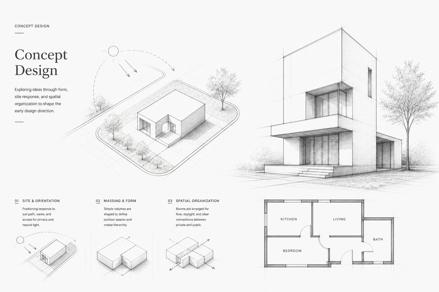
Illustration by ArchitectureCourses.org. Concept design turns early site, form, and layout decisions into a direction before the building is developed in detail.
Where design ideas first take shape.
This is where ideas shift from loose thoughts to something others can follow. Drawings at this stage test massing, proportion, and feasibility before detail becomes important.
Architectural Sketching
Sketching starts it off. Quick freehand marks catch the spark of an idea. Accuracy doesn’t matter yet—just energy, form, and intent.
Conceptual Drawings
Next come block studies. These test massing, zoning, and spatial flow. They set the backbone of early design logic and start to show if a scheme can actually work.
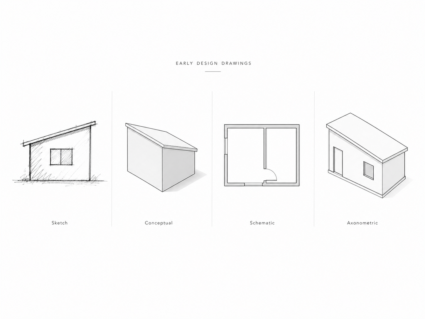
Illustration by ArchitectureCourses.org. Early design drawings can show the same building idea as a loose sketch, a massing study, a schematic floor plan, or a clean axonometric view.
Schematic Drawings
Schematic sets bring order. Rooms find their shape, walls shift into place, and materials start to appear. This is the first package most clients see, and often the first time costs get tested.
Axonometric Drawings
Axonometrics add 3D clarity without perspective distortion. They expose circulation and structure at scale. Often used in competitions or early reviews, they communicate intent cleanly to both architects and non-architects.
Architectural Drawing Explained: Plans, Details, and Permits
Floor Plans, Elevations, and Sections: Core Drawing Types in Architecture
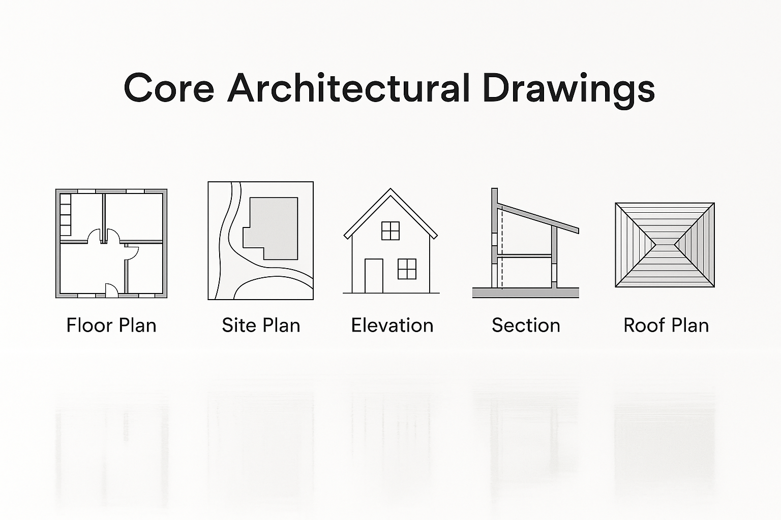
Core Architectural Drawings
The backbone of every project. Without them, nothing gets priced or built.
Essential Architectural Drawings Every Project Needs
These are the backbone of every project. Without them, nothing can be priced, permitted, or built.
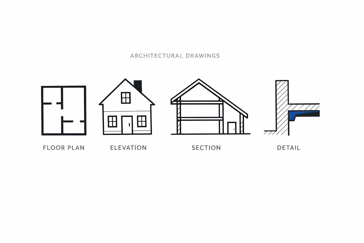
Floor Plans
A floor plan is a horizontal cut through the building. It shows rooms, walls, doors, and windows. This is usually the first drawing clients understand and the one contractors use to set out work.
Site Plans
Site plans put the building in context. They show lot lines, setbacks, access, landscaping, and utilities. Cities require them for permits, and they prevent costly mistakes in grading or layout.
Elevations
Elevations are straight-on views of the exterior. They reveal materials, openings, and proportions. They’re often the first impression of a design and help communicate style to both clients and planners.
Sections
Sections are vertical cuts through the structure. They show how floors stack, ceiling heights, and stair relationships. They also reveal wall build-ups, making them essential for coordination with engineers.
Roof Plans
Roof plans document slopes, drainage, chimneys, and skylights. They are critical for waterproofing and structure, often overlooked until problems arise on site.
See also: Architectural Drawing Symbols: Complete Guide for Students and Professionals
Clear guide for students, architects, and homeowners.
Architectural drawing types explained: from floor plans to construction sets.
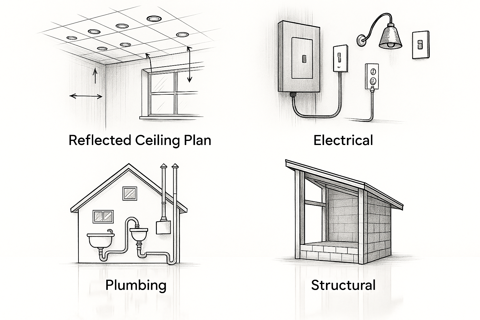
Engineering-Linked Architectural Drawings
Systems and Specialized Plans
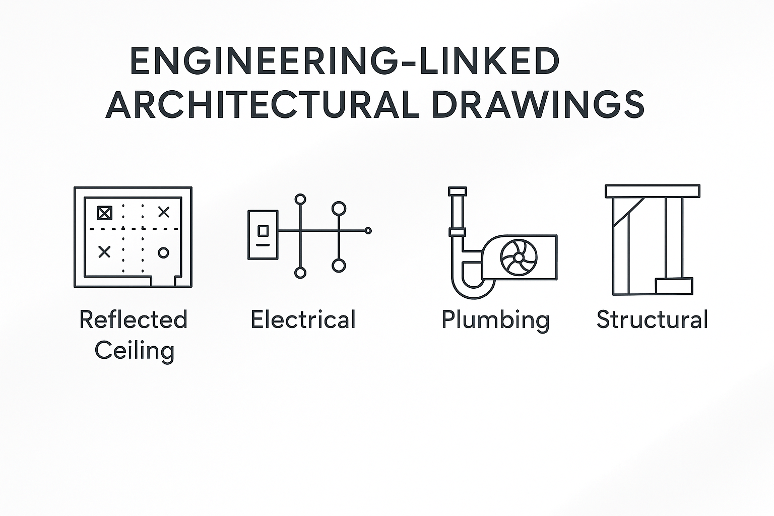
Drawings that overlap with engineering. They make the building work.
Drawings That Make Buildings Work
These drawings overlap with engineering but remain essential in architecture. They make the building safe, functional, and compliant.
Reflected Ceiling Plans (RCPs)
RCPs show lighting layouts, ceiling heights, vents, and sprinkler heads. They ensure all systems above your head align with the architectural intent.
Electrical Plans
Electrical drawings map outlets, switches, panel connections, and emergency lighting. They are a code requirement and prevent costly coordination errors on site.
Plumbing Plans
Plumbing layouts trace pipes, fixtures, vent stacks, and drainage slopes. They keep water supply and waste systems efficient, reliable, and properly sloped.
Mechanical/HVAC Plans
These drawings organize heating, cooling, duct runs, fans, and airflow. Comfort, efficiency, and building code compliance all depend on them.
Structural Drawings
Structural sets detail foundations, beams, columns, and reinforcement. They ensure the building stands and withstands loads safely.
Specialized Design & Detail Drawings
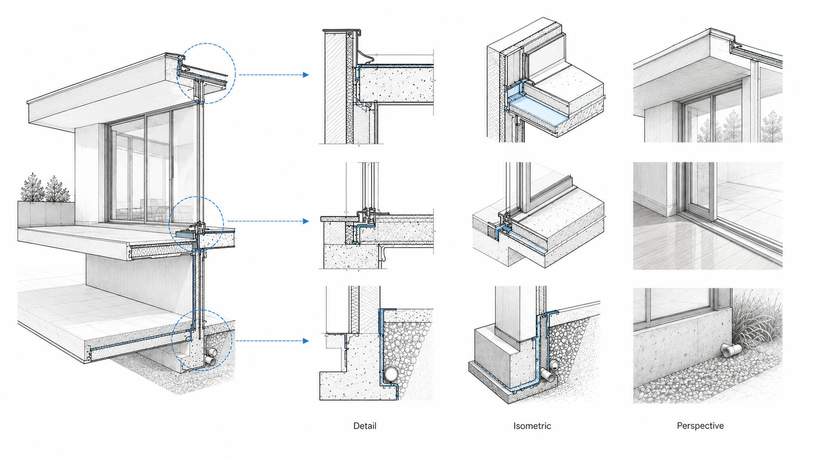
Illustration by ArchitectureCourses.org. Specialized design and detail drawings zoom in on junctions that plans and elevations cannot explain clearly enough for construction.
Where architects zoom in and explain parts that can’t be shown in a plan.
Detail, Isometric, and Perspective Drawings
Zoomed-In Architectural Drawings
These drawings handle what floor plans, sections, and elevations cannot. They zoom in on connections, materials, and real-world assembly. Without them, small mistakes on paper become costly problems on site.
Detail Drawings
Detail drawings enlarge critical points like stair junctions, door frames, and wall edges. They show materials, dimensions, and how layers fit together. On construction sites, they are the most referenced drawings because they prevent errors and disputes.
Isometric Drawings
Isometric drawings present three-dimensional visuals without perspective distortion. Unlike perspectives, they keep all scales equal, which makes them reliable for technical use. Contractors use them to see how systems and components align in space, especially in mechanical or joinery work.
Perspective Drawings
Perspective drawings show space as the human eye would see it. They were once painstakingly drawn by hand, but now digital rendering tools create them quickly. These are not technical documents but persuasive ones, used to help clients picture the final result before it’s built.
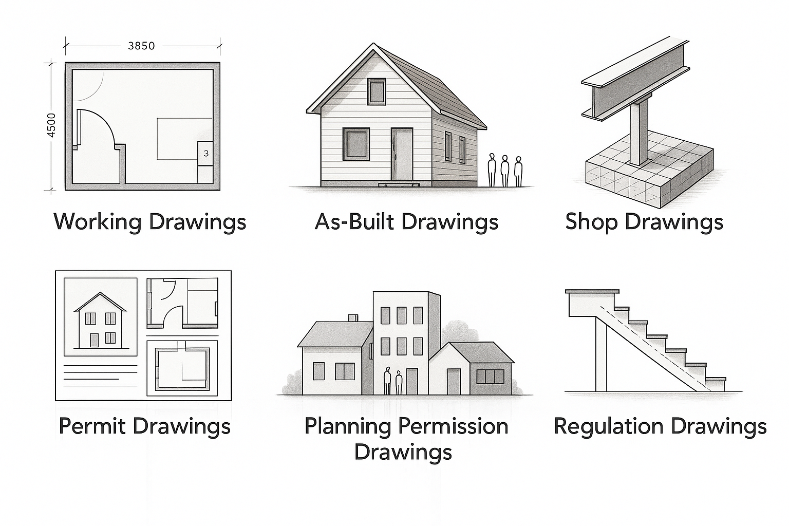
Working and Compliance Drawings
Construction & Regulatory Drawings
Drawings used by builders, inspectors, and permitting offices.
Permit, Code, and Site Approval Drawings
These are the sets that move a project from the architect’s desk to the building site and into legal approval. They balance technical precision with compliance requirements.
Working Drawings
The full technical set used on site. They specify sizes, materials, finishes, and connections so builders know exactly what to build.
As-Built Drawings
Updated records of the building as constructed. They capture last-minute changes and site adjustments, creating an accurate archive for maintenance and future renovations.
Shop Drawings
Produced by subcontractors such as steel fabricators, cabinetmakers, or HVAC installers. They show how components will be built and fitted, and must be reviewed by the architect for accuracy.
Permit Drawings
A simplified set prepared for city approval. Usually includes floor plans, elevations, and a site plan. Enough to prove compliance without overwhelming detail.
Planning Permission Drawings
Required where massing, height, or neighborhood context is under review. They demonstrate how the project sits alongside adjacent buildings and streets.
Regulation Drawings
Focused on code compliance. They highlight fire safety, insulation, structure, and accessibility to meet legal standards before construction begins.
Site and Outdoor Space Drawings
Landscape Drawings
How outdoor space ties into the architecture.
Landscape Architecture Plans
These drawings connect the building to its outdoor setting. They guide grading, planting, circulation, and the relationship between built and natural space.
Landscape Architecture Drawings
Used to plan grading, planting, paving, and site circulation. They balance function with aesthetics, ensuring that outdoor areas feel intentional and usable.
Landscape Perspective Drawings
Concept visuals of outdoor space, showing how gardens, paths, and courtyards will feel once complete. Often used to help clients visualize the flow between building and landscape.
Survey & Existing Condition Drawings
The baseline for any renovation or historic work.
Measured and Historic Documentation
Before design can begin, architects need an accurate picture of what already exists. These drawings are the baseline for renovations, additions, or historic preservation.
Measured Drawings
A direct survey of existing conditions. Walls, windows, doors, and floor levels are carefully recorded to ensure new design work aligns with reality. Accuracy here prevents costly mistakes later.
Renovation Documentation
Used to track what is being demolished, altered, and rebuilt. Often color-coded or hatched to clearly show old versus new, making it easier for contractors and inspectors to follow.
Historic Documentation
A precise visual record created for heritage buildings and archives. These drawings capture original construction details so future architects and historians know exactly how the structure was built.
Layered Construction Visuals
Exploded & Cutaway Views
Used for teaching and explaining how buildings fit together.
Teaching and Diagrammatic Drawings
These drawings are designed for teaching, presentations, and showing how different pieces of a building come together. They reveal structure and assembly in ways standard plans and sections cannot.
Exploded Views
Each major element—roof, floors, walls, and structure—is separated but kept in alignment. This lets viewers see how components stack, connect, and depend on one another without hiding anything.
Cutaway Views
A hybrid of section and elevation. Part of the building is sliced away so the interior is visible, while the exterior remains intact. It’s a powerful tool for showing both outer form and inner function at once.
From Orthographic to BIM
Technical & Visualization Drawings
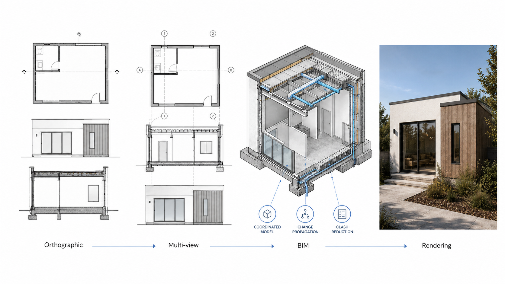
Illustration by ArchitectureCourses.org. Technical drawings move from flat orthographic views to coordinated BIM models and renderings that help check structure, services, and final appearance.
Where architecture meets digital and engineering clarity.
Digital and Engineering Representation
This category bridges pure technical precision with the visual clarity clients expect. It covers the shift from flat orthographic drawings to digital models and full renderings.
Orthographic Projections
The foundation of technical representation. These 2D scale drawings strip away perspective and show dimensions exactly. They are the bedrock of accuracy in architecture.
Multi-view Technical Drawings
Plans, sections, and elevations combined to give a full technical picture. Together they cross-check design and prevent errors by showing the building from all critical angles.
3D BIM Models
Unlike static drawings, Building Information Models are living digital files. Change a wall in one view, and the update flows through the entire set. They merge architecture, structure, and services into a single coordinated system.
Digital Renderings
These turn technical drawings into client-facing visuals. Photorealistic images and animations show materials, light, and atmosphere long before construction. Today, they are as much a marketing tool as a design aid.
Drawings as Investment, Not Paper
Costs and Practical Value of Drawings
Why drawings are more than “paper.”
What Architectural Drawings Are Really Worth
Architectural drawings are often the most visible part of what architects produce. They may look like sheets of paper, but they carry real cost and measurable value.
Price of Architectural Drawings
For a small home, a complete drawing set can cost a few thousand dollars. For large projects, the figure climbs into six figures. The price reflects not just time spent, but the liability and precision behind them.
Role in Construction
Good drawings reduce mistakes on site. Clear details and coordination prevent costly errors, change orders, and delays. Every dollar spent on careful drawings often saves multiples of that during construction.
Client Value
For clients, drawings are the most tangible output of an architect’s work. They make ideas real, communicate design intent, and give builders instructions to deliver the project as promised.
Mistakes to Avoid
Weak or incomplete drawings cost far more than they save. Missing dimensions, vague details, or poor coordination between drawings lead to delays, contractor disputes, and expensive fixes. A common example is stair construction: if riser heights or headroom aren’t coordinated between plans and sections, builders may install stairs that don’t meet code. Fixing that mistake after framing often means tearing out whole flights, adding weeks of delay and thousands in rework.
How Architects Learn to Draw
Beginners and Learning Path
Where future architects build skill.
From Sketching to CAD: A Student’s Path
Every architect starts with drawings. The skill builds step by step, moving from observation to technical precision.
Architectural Sketching for Beginners
The first step is freehand sketching. Students learn to observe space, light, and proportion with quick pencil marks. These sketches train design thinking and visual memory before software enters the picture.
Transition to CAD
Once the basics are in place, students move to digital tools. AutoCAD, Revit, and other software replace pencil lines with precision. The jump is less about abandoning hand work and more about learning to think in scale, accuracy, and data.
Learning Detail
Sections and detail sketches come next. By cutting through walls, floors, and joints on paper, beginners learn how materials connect. These exercises sharpen the eye and prepare students for real construction drawings later in their training.
MUST READ
The Language of Architecture: 26 Principles Every Architect Should Know by Andrea Simitch and Val Warke
This book breaks architecture down into 26 clear principles. Think of it as the alphabet of design. Each chapter covers one element—like scale, rhythm, or light—and shows how it has been used across history and in modern practice. It’s not a heavy theory book. It’s a visual reference you can keep on your desk and flip through for ideas. Architecture students use it to build a foundation. Practicing architects use it as a refresher when a project feels stuck.
The medium is changing, but the logic remains.
Where Architectural Drawings Are Going
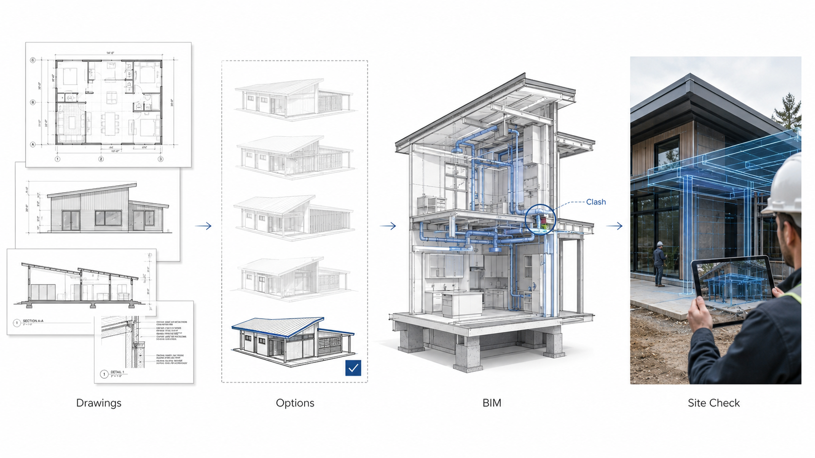
Illustration by ArchitectureCourses.org. Modern architectural drawings move from separate sheets into coordinated models that help catch clashes and check work before mistakes reach the site.
The tools are shifting, but the purpose is the same: clarity, coordination, and control on site.
Parametric and Computational Drawings
Why it’s happening: buildings face tighter energy, cost, and performance demands. Algorithms can test thousands of design options in seconds.
Is it a good thing? Yes, when used with purpose. Without clear goals, it becomes gimmicky.
Example: Zaha Hadid Architects used parametric tools on Beijing’s Daxing Airport roof to balance daylight and structural span.
AI-Assisted Sketching
Why it’s happening: AI can generate quick variations, speeding up concept work.
Is it a good thing? It saves time, but can lead to lazy design if architects stop refining. AI doesn’t know context or culture.
Example: Firms like Gensler are testing AI tools for interior layouts, but they still rely on designers to pick what makes sense for clients.
Integrated BIM Workflows
Why it’s happening: traditional 2D sheets cause errors when changes don’t get updated everywhere. BIM keeps drawings and data in sync.
Is it a good thing? Yes, but it demands training and setup. Small offices often struggle with the steep learning curve.
Example: The new Oslo Opera House renovation phases were coordinated entirely through BIM to avoid conflicts between steel, glass, and concrete systems.
AR and VR Overlays
Why it’s happening: clients and builders want to see space before it’s built. A 2D plan often fails to communicate scale.
Is it a good thing? Extremely. It reduces expensive on-site changes. But VR can also oversell visuals that don’t fully match reality.
Example: Healthcare projects in the US now use VR mockups so surgeons and nurses can test operating room layouts before construction.
Can AI Create Architectural Drawings?
AI can sketch, but not build-ready yet
Current tools like Midjourney, Spacely, and Maket AI can spit out quick floor plans or facades. They’re great for concept ideas, but the drawings don’t hold up to technical standards.
Accuracy is still the gap
Walls drift, stairs don’t meet codes, and proportions get warped. This is why CAD and BIM remain the backbone for anything real.
Where AI is useful today
Firms already use AI to run daylight studies, generate massing models, or catch inconsistencies in large drawing sets. It speeds up grunt work, not the final permit set.
The future is integration
The real change will come when AI plugs directly into BIM and drafting platforms. That’s when it could start producing code-compliant drawings. We’re not there yet, but the direction is clear.
How to Create Your Own Drawing Set
Making drawings is harder than reading them. A set is not decoration. It’s a construction roadmap, and every error costs money.
Clarity First
Each sheet should answer one question: what does the builder need to know?
Don’t flood pages with notes. Builders tune out clutter.
Consistency Always
Keep line weights, fonts, and symbols uniform. A door tag should look the same on every sheet.
Label tight. If a window is “W-01” in plan, it must be “W-01” in elevation and detail. Big firms lock this down with CAD/BIM standards.
Think Like a Builder
Could someone build the room with only the sheet in front of them? If not, you’re missing detail.
Good sets scale in layers: big picture first, then details, then notes. Keep that order.
Add Your Edge
Students and interns sometimes add axonometrics, diagrams, or color-coding to make a set clearer. If it helps the reader, it belongs.
But clarity beats decoration. A clean sheet always wins over a beautiful but confusing one.
Conclusion
Architectural drawings are still the backbone of design. From the first rough marks to full BIM models, they stay the link between an architect’s idea and the building that gets made.
Glossary of Terms:
A comprehensive glossary of terms commonly used in architectural drawings.
A
- As-Built Drawings: Drawings that reflect the actual dimensions and conditions of a building project as it was constructed.
- Axonometric Drawing: A type of projection used in architectural drawing that represents three-dimensional objects on a two-dimensional plane with all three axes drawn to scale but without perspective.
B
- Blueprint: An outdated method of reproducing architectural drawings that resulted in white lines on a blue background. Modern equivalents are now typically produced digitally.
- Building Envelope: The physical barrier between the interior and exterior environments of a building, including walls, floors, roofs, windows, and doors.
C
- CAD (Computer-Aided Design): Software used by architects and engineers to create precise drawings and models of buildings and structures.
- Cross Section: A vertical cut through a building or structure, showing internal components and materials.
D
- Detail Drawing: An enlarged view of a specific part of a building, showing how components fit together.
- Dimension Line: A line on a drawing that shows the measurement of an object or space.
E
- Elevation: A flat representation of one side of a building, showing height, materials, and design details.
- Egress: A way out of a building or structure, especially an emergency exit.
F
- Floor Plan: A horizontal cut through a building, showing the arrangement of rooms and spaces from above.
- Footprint: The area of ground covered by a building or structure.
G
- Grid: A network of evenly spaced horizontal and vertical lines used to arrange and organize elements on a drawing.
H
- Hatch: A pattern used on drawings to indicate different materials or areas.
I
- Isometric Drawing: A type of axonometric drawing where all three axes are shown at equal angles, providing a three-dimensional representation without perspective distortion.
J
- Joist: A horizontal structural element that supports floors or ceilings.
K
- Key Plan: A small-scale plan used to show the general arrangement of a building or area.
L
- Legend: A list or chart that explains the symbols and abbreviations used on a drawing.
- Lintel: A horizontal support across an opening, such as a door or window.
M
- Mechanical Drawing: A detailed plan that shows the mechanical systems of a building, including HVAC, plumbing, and electrical systems.
- Model: A three-dimensional representation of a building or structure, used for visualization and planning.
N
- North Arrow: A symbol on a drawing that indicates the direction of north.
- Notation: Written notes and labels on a drawing that provide additional information about the design.
O
- Orthographic Projection: A method of drawing a three-dimensional object from multiple directions, typically showing the top, front, and side views.
P
- Perspective Drawing: A drawing method that represents three-dimensional objects on a two-dimensional plane with converging lines to create depth and realism.
- Plan View: A view from above, showing the layout of a building or space.
Q
- Quantity Surveying: The process of estimating and managing the costs and quantities of materials needed for a construction project.
R
- Rendering: A visual representation of a design, often created with software to show realistic views of the finished project.
- Revit: A type of BIM (Building Information Modeling) software used for creating detailed architectural designs and drawings.
S
- Section: A cut-through view of a building or structure, showing internal details and materials.
- Site Plan: A drawing that shows the layout and features of a building site, including the building footprint, landscaping, and access points.
T
- Title Block: The area on a drawing that contains important information such as the project title, date, scale, and architect's name.
U
- Underpinning: A method of strengthening the foundation of an existing building.
V
- Veneer: A thin layer of high-quality material, such as brick or stone, applied to the exterior of a building for aesthetic purposes.
W
- Working Drawings: Detailed drawings that provide the information needed to construct a building, including dimensions, materials, and installation details.
X
- X-Bracing: A structural element that provides stability to a building by forming an X-shape with beams or rods.
Y
- Yield Strength: The maximum stress that a material can withstand without permanent deformation.
Z
- Zero Lot Line: A type of development where a building is constructed up to or very near the boundary of the property.
FAQs
General Blueprint Reading
How do you read blueprints?
Reading blueprints involves understanding the symbols, lines, and scales used to represent the different elements of a structure. Familiarizing yourself with the legend and paying attention to the details provided in the drawings is crucial.
Is it hard to read blueprints?
It can be challenging initially, but with practice and understanding of the basic components, symbols, and scales, it becomes easier. Many resources and courses are available to help you learn blueprint reading step by step.
Is reading blueprints a skill?
Yes, reading blueprints is a skill that requires knowledge and practice. It involves interpreting technical drawings accurately to understand the design and construction details of a project.
What is the most important part of blueprint reading?
Understanding the scale and accurately interpreting the symbols and notes are crucial. Paying attention to detail ensures that you can visualize the design accurately and understand the construction requirements.
Technology and Tools
Is there an app that can read blueprints?
Yes, there are several apps available that can help read and interpret blueprints, such as PlanGrid, Bluebeam Revu, and Autodesk BIM 360.
Can AI read blueprints?
AI technologies are being developed to read and interpret blueprints, assisting in tasks such as error detection, cost estimation, and project management. AI can analyze large sets of data more quickly and accurately than humans.
Can blueprints be digital?
Yes, blueprints can be created, stored, and shared digitally using software like AutoCAD, Revit, and SketchUp. Digital blueprints allow for easier collaboration and modifications.
Blueprint Components and Symbols
What do symbols on blueprints mean?
Symbols on blueprints represent different components of a building, such as doors, windows, electrical outlets, and plumbing fixtures. A legend on the blueprint explains what each symbol means.
How to read blueprint measurements?
Blueprint measurements are usually given in feet and inches or meters and centimeters. It's important to understand the scale of the drawing to interpret these measurements correctly.
Professional Use and Applications
Do architects read blueprints?
Yes, architects create and read blueprints as part of their design and construction process. They use blueprints to communicate their designs to clients, builders, and regulatory agencies.
Who can read blueprints?
Blueprints can be read by architects, engineers, builders, contractors, and anyone involved in the construction process. Training in blueprint reading is often part of professional education in these fields.
How much can you make reading blueprints?
The ability to read blueprints is a valuable skill that can enhance job prospects in architecture, engineering, and construction. Salaries vary widely depending on the specific job role and level of experience.
Technical Aspects
What is the difference between a schematic and a blueprint?
Schematics are simplified representations showing the functional relationships of a system, while blueprints are detailed drawings used for the actual construction of buildings and other structures.
How to read a blueprint for manufacturing?
Reading a manufacturing blueprint involves understanding technical drawings that include detailed information about the dimensions, materials, and assembly instructions for manufacturing parts and products.
Concept and Methodology
Why is it called blueprints?
The term "blueprints" originated from the cyanotype process used to produce copies of technical drawings. The process resulted in white lines on a blue background, hence the name "blueprints."
What is the main purpose of blueprints?
The main purpose of blueprints is to provide a detailed and accurate visual representation of a design, ensuring that all parties involved in the construction process have a clear understanding of the project's requirements.
Advanced Questions
Do blueprints use math?
Yes, blueprints involve a significant amount of math, including geometry, algebra, and trigonometry, to ensure accurate dimensions, scaling, and structural integrity.
Is Blueprints a programming?
No, blueprints in this context refer to technical drawings used in architecture and construction. However, in software development, "Blueprints" can also refer to a visual scripting system used in game design, such as in Unreal Engine.
How to read plan drawings?
Plan drawings are read by understanding the layout of a structure from a top-down perspective. They include details about room sizes, wall placements, doors, windows, and furniture arrangements.
Miscellaneous
Why are blueprints blue?
The original blueprints were blue due to the cyanotype printing process, which produced a cyan-blue background with white lines. This method was cost-effective and durable for creating copies of technical drawings.
What is the benefit of a blueprint?
Blueprints provide a clear and detailed visual representation of a design, facilitating accurate construction and ensuring that all stakeholders have a consistent understanding of the project requirements.
Related
Blueprints & Plan Reading
-
What Are Blueprints in Construction and Design – Explains the role of blueprints in building and design projects.
-
Reading Blueprints: How to Read Plans Like a Pro – Step-by-step guide to understanding floor plans and technical drawings.
-
How to Draw Your Own House Blueprints – Practical tips for sketching your own home plans.
-
Drawing of a Modern House: Reading and Creating Your First Plans – Learn how to read and draft a basic house design.
Architectural Drawing Basics & Techniques
-
Architectural Drawing Symbols: Complete Guide for Students and Professionals – Explains the most common drawing symbols used in architecture.
-
Basic Techniques and Principles of Architectural Drawing – Foundational skills every student and professional should practice.
-
Blind Contour Drawing: From Basics to Advanced Techniques – Training method for improving hand-eye coordination in drawing.
-
Basic Drawing Tools for Architects: Top Picks and Personal Favorites – Recommended tools that architects rely on for sketching and drafting.
-
List of Architectural Drawings – Overview of the different drawing types used in projects.
-
Easy Architecture Drawing: The Exact Process I Use to Teach New Students – A simple approach to teaching beginners architectural sketching.
-
The Art of Drawing a Simple Line in Architectural Sketches – Shows how even simple lines shape expressive drawings.
References
American Institute of Architects (AIA)
The AIA offers a wealth of resources for professional development, networking, and advocacy. Membership benefits include access to exclusive events, continuing education opportunities, and publications.
Royal Institute of British Architects (RIBA)
RIBA is a global professional membership body driving excellence in architecture. It provides support to members through professional standards, training, publications, and events.
National Council of Architectural Registration Boards (NCARB)
NCARB helps architects achieve licensure and certification. They provide resources for exam preparation, licensing requirements, and professional development.
Architectural Institute of Japan (AIJ)
AIJ promotes the advancement of architectural science and technology. They offer research publications, events, and networking opportunities for members.
International Union of Architects (UIA)
UIA is a global organization that represents architects worldwide. They focus on promoting architecture in service to society and supporting the professional development of architects.
American Society of Landscape Architects (ASLA)
ASLA represents landscape architects in the U.S. and offers resources for education, networking, and professional development in landscape architecture.
Construction Specifications Institute (CSI)
CSI provides standards and resources for construction documentation, specifications, and project delivery. Membership includes access to certification programs and professional development opportunities.
Green Building Council (GBC)
The GBC promotes sustainable building practices through its LEED certification program and offers resources for education and advocacy in green building.
References and Sources
Los Angeles County Public Works – Building and Safety
- Residential Minimum Plan Submittal Requirements (PDF)
- Building and Safety – Permits and Plan Check
- Plan Check – General Information
- EPIC-LA Electronic Plan Submittal Portal
- Plans Retention and Records FAQ
- Electrical Plan Check Checklist (PDF)
Standards and Best Practices
Books for Learning Architectural Drawing